Bulb and internal driver
Confirm the exact product code, electrical construction, rated voltage and whether the supplied version is dimmable.

Practical Guidance for Custom Decorative Bulb Projects
Product-based information for lighting brands, distributors, designers, contractors and commercial project buyers.
A “dimmable” label is only the starting point. Stable performance depends on the exact bulb, dimmer or control system, circuit load, supply voltage, fixture and required low-light range.
This guide helps lighting brands, wholesalers, designers, contractors and project buyers prepare a dimmable decorative-bulb requirement that can be tested and approved. GLORILUM can review dimmable and non-dimmable options for selected products, but the proposed combination must be confirmed for the target market and installation.
The bulb and its internal electronics respond to the waveform supplied by the control. The result also changes with the number of lamps on the circuit, the total connected load, wiring and the dimmer’s operating range.
For a project, approve the exact bulb version with the intended dimmer or control equipment. Do not treat a successful test on a different lamp, circuit or market voltage as universal approval.
Confirm the exact product code, electrical construction, rated voltage and whether the supplied version is dimmable.
Provide the manufacturer, model and control method. Similar-looking wall controls can behave differently.
One decorative bulb may be below a dimmer’s useful load range, while a large group can approach its stated capacity.
Fixture construction, shared controls, transformers, relays, smart devices and wiring can change the observed result.
Sending these details early is more useful than requesting a generic “dimmable bulb.” If any item is not yet known, mark it as pending so it can be tested before production.
State the target country or region, nominal supply voltage and frequency. Do not assume a 120V and 230V version will use identical electronics.
Share the exact model number, phase-cut direction or other control interface where known, plus any controller documentation.
Confirm the planned quantity of lamps, total load and whether other lamp types or devices share the circuit.
Define whether the project needs gentle adjustment or a very low decorative level. “Smooth dimming” without a target range is too vague.
Provide the base, fixture type, open or enclosed condition, and any transformer, smart relay or lighting-control equipment.
Select the bulb shape, glass finish and filament design because visible brightness and low-level appearance differ between products.
A replaceable decorative bulb, a fixture with a separate driver and a building-control system are not interchangeable specifications. Confirm the architecture before selecting the product.
Leading-edge or trailing-edge behavior depends on the exact dimmer and lamp electronics. The chosen combination should be tested at the planned circuit load.
For 0–10V, DALI or another building-control interface, the signal may be handled by a separate driver or fixture rather than by a standard screw-base bulb.
A non-dimmable version is often the clearer choice for fixed-output circuits, simple decorative displays and applications without a validated dimmer.
These are possible system-level causes, not remote diagnoses. Electrical testing and installation work should be handled by qualified personnel with the circuit safely isolated when required.
| Observed behavior | Possible factors | What to verify |
|---|---|---|
| Flicker or pulsing at low level | Dimmer-lamp mismatch, low circuit load, unstable low-end setting or other connected equipment | Exact dimmer model, lamp count, minimum setting and isolated test circuit |
| Light drops out before minimum | The lamp cannot remain stable below a certain control point | Usable dimming range and whether the dimmer’s low-end trim can be set |
| Pop-on or delayed startup | Starting threshold differs from the level used after the lamp is running | Switch-on tests from off at several control positions |
| Visible shimmer in a group | Shared control behavior, mixed lamp versions, wiring conditions or unit variation | Same production version, planned group size and installed mock-up |
| Audible sound | Interaction between dimmer, lamp electronics, fixture or supply conditions | Source of sound, exact equipment combination and alternative validated control |
| Uneven brightness between lamps | Mixed products, mixed batches, control distribution or tolerance at very low level | Product codes, sample group and acceptable low-level consistency |
A single sample on a bench is useful, but it does not represent every installation. The final approval should include the planned control, lamp quantity and a representative fixture or mock-up.
Continue to the Custom Lighting Guide →Low-wattage decorative lamps can present a very small load to a wall dimmer. Confirm stable startup and the useful lower range.
Test the planned number of lamps together and review synchronization, low-level consistency and total load.
Coordinate the bulb with the specified keypad, relay, dimmer module or room-management system before procurement.
Avoid assuming different lamp technologies or product versions will dim together in the same way.
Check what the smart device actually switches or dims and whether its output is approved for the proposed lamp load.
Record the approved lamp version, dimmer model, settings and sample so later production can reference the same system.
These product pages provide a real starting point. Confirm the dimmable version, voltage, base, glass, filament and target control system before specifying or ordering.
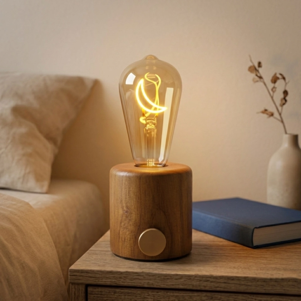
120V or 230V and dimmable or non-dimmable project options with clear, champagne or custom glass directions.
View product →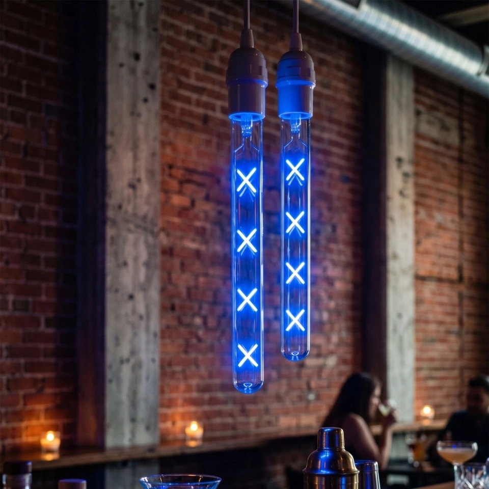
A long decorative tube reference with 85V–265V and dimmable or non-dimmable customization routes.
View product →
A broad clear-glass product with custom short wording, 120V or 230V and dimmable or fixed-output options.
View product →
A colored-filament reference where dimming, glass, perceived color and the proposed control should be reviewed together.
View product →The perceived result depends on the filament, glass and ambient light. A physical sample should be reviewed in the intended fixture at the levels the project will actually use.
Check glare, reflections and whether the filament is comfortable at both full and reduced output.
Approve the off-state color and the illuminated result; a photo cannot establish the final tint or dimmed appearance.
Darker glass can reduce filament visibility and perceived brightness, so check the useful lower range in daytime and evening conditions.
Confirm that words, symbols and colored filaments remain recognizable and stable at the levels planned for operation.
Use the same product version and planned control throughout the test. Record any dimmer settings and keep the approved sample with the project specification.
Confirm bulb, base, voltage, frequency, glass, filament and dimmable construction.
Check switch-on, full output, mid range, useful minimum and repeated off-on cycles.
Use the intended number of lamps and review synchronization, shimmer, sound and low-level stability.
Confirm visible appearance, temperature conditions and control behavior in a representative installation.
Retain the sample, control model, settings, product code and agreed acceptance criteria for production.
Do not approve only from a video. Camera exposure and frame rate can hide or exaggerate visible flicker and brightness differences. Review the physical system directly.
Prepare a dimmable sample request →Short answers to the compatibility and approval questions buyers should settle before placing a production order.
No universal compatibility should be assumed. The exact bulb electronics, dimmer model, circuit load and supply conditions all matter. Test and approve the proposed combination.
They are different phase-cut methods used by dimmers. Product behavior depends on the lamp and control combination, so identify the actual dimmer type and model instead of selecting only by the general label.
The lamp may be operating below its stable range, the circuit load may be unsuitable, or the dimmer-lamp combination may not match. Confirm the useful minimum during testing and follow the control manufacturer’s setup guidance.
Do not assume that setting a dimmer to maximum makes it equivalent to a normal switch. Use the electrical version intended for the circuit and follow the lamp and control manufacturers’ instructions.
They can only be approved after checking the exact product version, number of lamps, total load, dimmer capacity and low-end behavior. Test the planned group rather than extrapolating from one bulb.
Do not assume identical construction or behavior. Confirm the voltage, frequency, target market and proposed control separately for each version.
Usually the control interface is handled by a compatible driver, fixture or control module, not by every replaceable decorative bulb. Share the system diagram so responsibilities can be reviewed.
Send the bulb shape, glass and filament direction, base, voltage, frequency, target market, dimmer or control model, lamps per circuit, required lowest level, fixture details, quantity and schedule.
Share the proposed bulb, market power, control model, circuit quantity, fixture and required dimming range. We will identify the next product and sample checks.
Direct email: custom@glorilum.com
Compatibility & Project Testing
A lamp marked dimmable still needs to be evaluated with the intended dimmer, circuit and number of lamps. Compatibility is a system result—not a promise created by the word “dimmable” alone.
May appear only at certain levels, after warm-up or when other loads share the circuit. Record the dimmer position and operating condition.
The lamp may switch off before the control reaches its lowest position or may not start smoothly from a very low setting.
A faint glow after switch-off can be related to leakage current, illuminated switches, wiring or control design and should be checked on the real circuit.
Many dimmers specify an allowable load range. LED lamp wattage is much lower than traditional incandescent wattage, and a small group of decorative lamps may not meet a dimmer's minimum operating load. At the other end, do not judge capacity only by adding printed watts: driver inrush and the dimmer manufacturer's LED rating may also matter. Confirm the current technical documentation for the exact control.
A sample tested as a single lamp can behave differently when six, twenty or more lamps share a control. The final quantity per dimmer, wiring length, circuit arrangement and lamp mix affect the result. Do not mix unreviewed lamp models or drivers on one dimmed circuit when consistent low-end behavior is important.
| Test | Check | Record |
|---|---|---|
| Cold start | Start at full, middle and low settings | Reliable start point and any delay |
| Full dimming sweep | Slowly raise and lower output | Usable minimum, dropout, shimmer or noise |
| Warm operation | Repeat after normal operating time | Any change after components warm |
| Final lamp count | Test representative quantity and circuit | Dimmer, lamp model, quantity and wiring arrangement |
| Switch-off | Observe immediately and after a short period | Glow, flash or complete off state |
Coordinate electrical information with the voltage customization guide. For exposed-lamp comfort, also review the lumens and glare guide.
Send the lamp quantity, electrical market, fixture and dimmer reference. A representative test is the safest basis for project approval.
Request a dimming review →